Monday, May 11, 2015

Final Project Overview


This post will be a combined walk-through and reflection of my final project, an automated toilet flushing device.

Idea
Because the noise of a flushing toilet is so loud, children often get scared when they flush, or do not flush at all. To fix this problem, my partner and I aimed to create a device that, once a child has pressed a button indicating that they want the toilet to flush, will sense whether the child has left the stall or not. If the child has not left the stall, the flush will delay an appropriate amount of time to allow the child to leave. If our device senses that there is no child in the stall, the toilet will flush immediately.

Note: After talking to a director at the preschool, we determined that the appropriate delay time would be ten seconds.

How It Works
Our final piece, from the outside, was an opaque box that could be mounted on top of a toilet tank via suction cups, with only an ultrasonic sensor and a large yellow button visible. Once a child is ready to flush, she or he will push the button. Then our sensor, which is constantly detecting values, will determine whether a child is still in the stall based on a value that my partner and I have programmed into our code (detailed in post "Final Project Week 2"). If a child is detected in the stall, the program will delay for ten seconds and then signal to the motor to run in reverse for ten seconds then run forward for ten seconds. by doing this, a rod-type piece that is attached to the motor of the flushing device we purchased moves up and then down again, like the way that two gears might turn together. This up and down motion lifts a rod within the toilet that opens and then closes a valve, causing the toilet to flush. If no child is detected, the program will operate similarly just without the delay. The program then resets.

Our final piece from the outside.
Our final code.
Thoughts and Improvements: I would have liked to have built the flushing device by hand, and given more time we would have. We did have an original design for how we might do that (detailed in post "Final Project Week 1") but it required way too much force for the motors available to us. However, while we didn't build the device that actually flushes the toilet, it uses many things that we learned in class such as gear trains and converting circular motion to linear motion. I also would have liked to make the code more advanced, and I think that would be a good challenge for a future group to work on. Ideally, the code would be able to say that if a child was sensed, but the child leaves before the delay is finished, it is okay to flush before the end of the delay. Currently our code waits a fixed delay time if a child is sensed after the button is pushed. However, our code certainly still accomplishes everything we wanted our device to do and I'm pleased with the final outcome when we demonstrated our product in class (Unfortunately our prototype wasn't the most audience friendly for a demo because most of what visibly goes on is inside the tank).

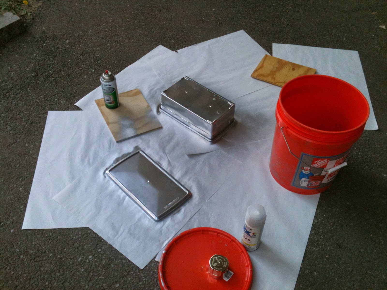
Putting It All Together
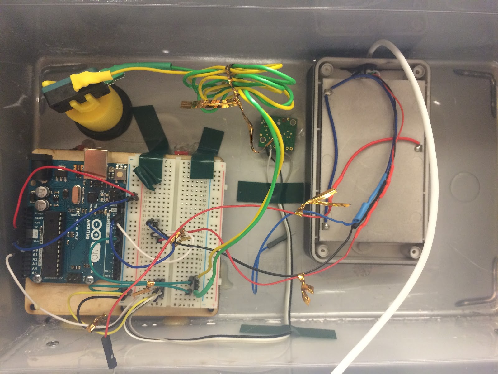
This part of the process was the most fun for me because it was the most hands-on. To house all of our parts (Arduino and breadboard, sensor, button and battery pack) we started out with a clear plastic box. It was important to us that the box be opaque so that the children wouldn't be tempted to go inside and potentially hurt themselves or mess up our device. This is why we spray-painted our box silver (most people thought it was metal from far away, which I thought was neat). Further, we cut holes in the box to house the sensor and the button, which need to be visible from the outside (detailed in post "Final Project Week 3"). Also, because the lid of the box stuck out over the edge, our box sat tilted on an angle when placed on its side. We thought that this might affect the sensor value readings, so to remedy that we glued a thick piece of Delrin to the side of the box, creating a level surface. Then we stuck suction cups on so that an instructor could easily remove the device from the toilet if necessary (we also made it easy to change the batteries). Everything inside the box required a lot of soldering (and re-soldering) to reinforce the bonds between the Arduino and the ultrasonic sensor, button and battery pack. From there we secured all of our parts inside the box and hooked up the flushing device to the toilet tank.

Thoughts and Improvements: Looking back I would have liked to use a box that looked cleaner cut and possibly more compact, just for the purpose of aesthetics. However our design was not messy fro the outside whatsoever and I do not think it would be difficult to install or look out of place in a bathroom. I also wish, although this might be minor, that we had found a way to make the holes in the box look cleaner, but sanding then down was the best we could think of to achieve this.

The inside of our device.
Final Thoughts
I felt that our final design looks simple and is unobtrusive enough to be used in any school — or home, for that matter. The director of the preschool had very positive comments about our product, saying that it could be sold in stores, which is an encouraging response. During the demonstration our product worked exactly as it should and even though is was difficult for the audience to see this, I'm actually pleased that the motor is so quiet, as this is an added feature of the product. Other than the improvements I suggested above, I am very pleased with the outcome of our project and am only sad that there isn't more time to continue improving upon it.

Olivia and me with our project.


Friday, May 8, 2015

Final Project Week 3

During our third week of working on our final project, we focused mainly on the setup of our piece, now that we had the code worked out. I will detail below the many steps we took to get to our final prototype.

Arduino

First we had to set up our Arduino and breadboard with all the correct wiring so that the button, ultrasonic sensor, and motor would all react to our code. This took a bit of rewiring but overall was not too challenging, mainly because we have had so much experience with Arduino in this class. Here's what the final setup of our Arduino and breadboard looks like:


Soldering

Because we were using a sample touch switch to function as our "button" while we tested the code, we now needed to attach our actual button to the Arduino. We learned that our wires needed to connect to the "normally open" setting on the button, which means that no current will flow when the button is unpressed, and current will flow through when the button is pressed. Soldering was one of our difficulties during this project, as many times our first soldering job wasn't strong enough to hold the wires. We also needed to fortify the bond on the ultrasonic sensor we by soldering the wire connection. It was often frustrating because we would have already attached all our pieces together only to find that a wire had broken, causing us to have to cut many wires unnecessarily and reattach them. Here is a photo documenting some of the soldering process:

The Box

Next, we had to worry about setting up the box which would contain all of our parts. It was important that the box not be clear so that the children would not feel tempted to open it and play with potentially dangerous wiring and/or break our device. To ensure that neither of these would happen we decided to spray paint our box an opaque silver.


Further, we needed to make three different cuts into our box. First, we needed to make a small hole in the lid of the box, which would be facing toward the back when mounted on top of the toilet, so that the wire connecting the motor to the battery pack would have a place to come out. We did this using a band saw and a box cutter, then we sanded it down to make sure there were no rough edges. Second, we needed to make holes for the button and the ultrasonic sensor to stick out. To do this we measured their diameter and used a compass to draw the appropriate circles on a sheet of paper. We then taped these paper circles onto the box where we wanted the holes to be. We used a very small drill on the drill press to drill holes along the circumference of each circle. From there we used a box cutter to cut out the circles from the box and finally sanded down the holes to make them smooth and safe. 

After this process, we were able to insert our button and sensor into the box. Here is what the outside of our piece looks like:

We also attached the other components such as the Arduino and battery pack to the inside of the box using both glue and tape. We made sure the battery pack was able to be removed as well so that the batteries could be replaced when necessary. Here is a photo of the inside of the box:
                      IMG_3358.JPG


On my next and final post about this project I will discuss the presentation and demo of our prototype as well as reflect on the process.

Wednesday, May 6, 2015

Final Project Week 2

During our second week working, we focused on getting our code right, which took several tries. Below, I'll detail the steps we took to get to our final code that will be used to make the toilet flush.

Goal: Just to be clear, I'd like to briefly outline what it is we were trying to get our code to do so that the photos and descriptions below might be easier to understand. Initially, we want our code to do nothing. However after a child presses a button, we would like the ultrasonic sensor to begin reading values. If the sensor reads a value that indicates a child is present, the toilet should do nothing for a certain amount of time, allowing the child to leave the stall, and then flush. Additionally, if the sensor does not sense a child, it will flush immediately. Note that the original flush handle attached to the toilet will still work on its own if need be.

That being said, our first iteration of the code was broken down into four parts. First, there is a while statement addressing the situation in which the button is unpressed. The motor stays off during this. Then, once the button is pressed the code breaks out of the while statement and follows a series of if statements. The first if statement adresses the situation when the time is less than two minutes and there is a child in the stall, the toilet should do nothing. Second, if it has been less than two minutes and there is no child in the stall, the motor will flush the toilet. Lastly, if the time is greater than two minutes the toilet will flush, regardless of whether or not there is a child in the stall.


However, this code failed to work when we tested it. The  ultrasonic sensor would only read values when the button was being held down, instead of just after it was pressed. Or, alternately, depending on where we put certain parts of the code, the sensor would read one value when the button was pressed and wait until the code had run through its full loop to read a second value. 

At this point we were concerned with whether or not our button was working correctly on its own. So we made a new code to simply test our button by making the motor function solely as a function of the state of the button. 

As it turned out, our button worked correctly. This told us that our problem was with the Millis function. So, we decided to remove that piece of the code and simply use a delay instead. In addition, we also simplified our code from being in four parts to three. Instead of having three separate if statements according to the time, we now only have two that are associated with only the value of the sensor reading. Our code now states that if there is no child in the stall, flush, and if there is a child in the stall, wait a certain amount of time and then flush. This simplification took us a great deal further on the road to our final iteration. 


Our final code, below, looks similar to the one above but with some adjusted values. After talking to a director of the preschool, we determined the child only needs ten seconds to exit the stall, so that was adjusted in our code. Here is our final version:


For my next post I will discuss the physical setup of our prototype and the different aspects of making it come together.

Monday, April 27, 2015

Light/Dark with Sciborg

Our last task with our sciborg was to get it to follow a white stripe using a brightness sensor. First, we had to do it using bang bang control, then proportional.

For bang bang control, we first tried writing a code that drove straight when it sensed it was on the light surface and turned back and forth when on a dark surface in the hope that it would find the light surface again and continue driving straight. Here is what the code for that looks like:
 

This code was unsuccessful however, because once on the dark surface, our sciborg was not able to reach the white line again. Or, if it did, it had gone in a full loop before reaching it again.

We then decided to use edge following, where turns right when on dark surfaces and left when on light surfaces. This worked very well and our sciborg was able to follow the track made by the white line. Here is our final code and  a video:

Next we tried to adjust our code so that our sciborg followed the line using proportional control. This was a difficult concept for us at first, because we couldn't figure out how to tell our sciborg how much it was on light or dark, we only knew how to tell it light vs. dark. However, after playing around with our code enough we found a way to implement proportional control by making the light value our "goal" and by calculating a reasonable gain. This way, we were able to create an "error" value based on how far our reading was from our goal value. We calculated an output equation using the gain and the error and set our speeds to output. After having to change our numbers several times and do many trials, this is what our final code looked like:


Notice that we put absolute value "bars" around our error function to account for our sciborg veering off the white line to the left or right. This ensures that our output is always positive. As a result of this adjustment, our sciborg did not zig-zag so sharply when following the line, instead making gentler adjustments to stay on track. Here is a video of our sciborg running the track using our proportional control code:


This completes our work with sciborgs and I will now be focusing my blog posts on my final project. 


Wednesday, April 22, 2015

Final Project Week 1

For our final project, my partner and I have decided to create a system so that the children have time to leave the bathroom stall before the toilet flushes, as they are often afraid of the loud noise.

Our first idea was to have the children push a button when they are done, and the button would triger an ultrasonic sensor to start sensing as well as timing. If it senses that a child is in the stall, the toilet will not flush. If it senses that there is no child, the toilet will flush. And, just in case, if it has been more than two minutes and the toilet still has not flushed, the toilet will flush.

In order to flush the toilet, my partner and I created a design using the Lego Bricktronics motor. When the toilet is cued to flush, the motor will turn for a specified time, which will turn a handle that is attached to it, which will then push the flush handle down. The handle will stay down for a couple seconds and then reverse the process to it's original position, completing the cycle of the system.

Here is what the toilet looks like at the preschool:


Below are some foam prototypes of our design (button and sensor not included in the prototype):


The foam box is to prevent the children from touching the flushing device and to protect it from any water. 


However, this design ran into some problems when we used a spring scale on actual toilets to measure the force needed to flush a toilet. The motor we currently want to work with does not have enough torque to successfully push down the flush handle. We are currently exploring other options and I will post again soon with a progress update.

Wednesday, April 15, 2015

Thermal Systems

Recently we have been using MATLAB to investigate thermal systems and how we can manipulate and simulate them using code.

For our thermal system, we are looking at the heating a cooling of a cup of coffee. First, we need to understand some basics of the system. The heat capacity, C of the coffee is defined as the ratio dE/dT, which measures the change in energy (or the energy flow) against the change in temperature, T. Now we need to look at the thermal resistance of the system, which is affected by the temperature difference (between the coffee and the air) and the heat flow. Basically, thermal resistance is asking how much the change in temperature drives the heat flow of the system, and can be written as

Rth = T-Tair/(dE/dt)

where t is time. Thus, to find the temperature change dT over the specified time dt, we get the formula:

dT = dE/C = dt* -(T-Tair)/(RthC)

Question 1
Since Rth and C both lie in the denominator of the equation for dT, by increasing them you get a small rate of change of temperature, meaning the coffee will cool more slowly over time. On the other hand, by decreasing Rth and C, you speed up the cooling process. Note that the negative sign on the lefthand side of the equation tells us that it is cooling, not heating up.

Now, suppose we add a heater to the coffee, so we are adding thermal energy into the system. In this scenario, we can write the rate of change as

dT = dE/C = ((P/C) - (T-Tair/RthC))*dt

Question 1
Now, if we want our coffee to be at 84 degrees centigrade, or 357 kelvin, we need to calculate P, the power supplied by the heater. Setting dT equal to zero, we also know that room temperature is 293 kelvin. We will use 1000 as our heat capacity and .85 as our thermal resistance. Plugging in, we get

0 = ((P/1000) - (357-293/.85(1000)))*10

64/.85 =P

P = 75.3

Below I will show you the programs on MATLAB that simulate the cooling and heating of coffee. For the heating, I will show both bang bang and proportional control of the heater, using the P value we found. 

Cooling


This code does not use P because there is no energy being put into the system, it merely simulates the temperature loss of the coffee over time as it approaches room temperature.

Heating: Bag Bang


As you can see, with bang bang control the coffee heats up the coffee quickly, supplying too much power at first, then when it reaches its ideal temperature, the heating shuts off completely. This is why the horizontal line segment of the graph looks so think, because the temperature is quickly rising and then dropping as the heat turns on and off.

Heating: Proportional Control

With proportional control heating, you will see that the curve of the graph is not as sharp as that of the bang bang heating graph. Here we implemented our P value at the desired temperature and varied it depending on the surrounding temperatures.


Proportional and Bang Bang Heating with Delay

Now we suppose that there is a 5 second delay between the time the the coffee reaches a given temperature and the time the sensor records it. To remedy this error, we will adjust our code on both the bang bang and proportional control heating codes to reflect a time recording that is five seconds earlier, so that the temperature being recorded matches the real temperature of the coffee.


As expected, these graphs record the temperature at an earlier time than on the graphs that did not account for the delay. Now the the correct temperature is recorded at the correct time.

This completes our investigation into thermal systems, but we'll continue to work with MATLAB.


Tuesday, April 14, 2015

MATLAB exercises

This past week we have been learning the basics or MATLAB, and were asked to complete a series of exercises in order to get to know the program better, which I will detail below.

Exercise 2.1

To begin, we were asked to write a code that would compute the nth term of the fibonacci sequence. The fibonacci sequence defines the first two terms as 1, and then each following term is the sum of it's two preceding terms. This is the code we wrote:


Note that we defined n=10 as a precondition. This successfully computed the nth term.

Exercise 2.3

Next, we were asked to write a script that had variables that were dependent on each other. In this case, there are two locations that each start out with 150 cars. Each week, five percent of the cars in location "a" leave to go to location "b", and 3 percent of the cars in location "b" move to location "a". our first task was to write a script that shows the final amount of cars after one week.

Note that our preconditions were to define "a" and "b" to be 150, to set a start value. You can see that after running the program (and rounding the numbers to the nearest whole integer) the adjusted values were produced.

Exercise 3.1

Now, we had to implement a loop into the function from 2.3 to account for 52 weeks. For this we used the integer "i" to count up to the number of weeks we wanted it to run for.


The final values look the same as the ones in 2.3 because I rounded the numbers to integers to begin with and after a certain point (number of weeks) the answers begin to stabilize until the number of cars in each location are the same from week to week.

Exercise 3.2

Now we added a plot to our script to see what the car transfers look like over time. Here is a photo of our sketch implementing the plot command and of our plot.


"ro" means to plot the "a vs. i" values in red circles. "bd" means to plot "b vs. i" as blue diamonds. 


You can see the values are more erratic at the bottom and then quickly level out. With initial values of "a" and "b" at 10000, it was easier to see the values change at the beginning. However since the function involves percentages it took the same amount of time fr the values to reach a stable output.

Exercise 3.5

For the next exercise, we wanted to compute the first ten numbers of the fibonacci sequence. We ended up printing the first 12 because we were printing "F", which is going up to te "i + 2th" term. We should have either said "i= 1:8" so that it would print the first ten numbers or we could have written "Print F(i-2)" to solve the problem. Either way we still found the 10th term of the sequence.


Exercise 4.6

For the last exercise we had to write a script that computes a vector for the "n+1th" term of the fibonacci sequence divided by the nth term. We would like to see if and where this converges. We had a lot of difficulties defining the "n+1th" term at first, but eventually we found a simple way to implement what we wanted. Then we plotted a graph.


You can see that it converges right above 1.6. 

This completes all of the MATLAB exercises, and soon I will post about thermal systems and more feedback & control.


Friday, April 3, 2015

Ideas for preschool project

Below are a few of my ideas for a project to implement at a preschool to aid the awareness of the children during daily activities like going to the bathroom, sitting still and washing your hands. I have pictures of rough sketches for most but not all of my ideas.

1: Bathroom lock

I was told that some children have trouble remembering to flush the toilet. To help correct this, I thought of putting a mechanism on the lock of the stall that forces the children to be mindful of whether or not they flushed. There would be a panel asking the child if he or she had flushed, and two buttons corresponding to yes and no. If the child selects yes, the bar that would be blocking the lock from being slid into the unlocked position would be raised using a gear and the child would be free to leave the stall. If the child selects no, this might trigger some sort of LED light reminding him or her to flush.

Potential problems: Child could get locked in the stall if he/she doesn't understand how to press yes. Child could learn to press yes without flushing. Time consuming machine.


2: Mats with ultrasonic sensor

I was also informed that children have trouble staying on their mats or carpet squares when they are supposed to. This then requires teachers to be constantly reminding them, which is tedious and frustrating. Instead, I thought giving them another response to pay attention to other than their teaher might be an easier way for the children to be aware of when they are getting up when they're not supposed to. For example, an LED light could go on. This way the teachers would only have to explain to the children to pay attention to their lights rather than repeatedly remind them to stay seated. An ultrasonic sensor could be attached to the mats somehow, or even multiple. This way, when the number goes past a certain specification, indicating that the child has moved too far away, a light is triggered to go on, reminding them to stay seated.

Potential Problems: The sensor could be too far that it detects other things, or too close that the readings are inaccurate. If the sensor is too visible it could be tempting to play with, but it can't be too hidden for the purpose of readings.


3: Mats with touch switches

Similar to the idea above, this idea is for an LED to go on after something has indicated that the child has moved too far from his/her mat. In this case, an array of touch switches would be spread out on the mat, underneath an added top layer of fabric. When the child sits, he or she will be pressing down on the touch switches. So, we can say that if maybe less than four of the touch switches are pressed, the child has moved too far from his or her mat and the light will turn on. 

Potential problems: Children often fidget or move, which could trigger the light accidentally. touch switches could break from the weight or constant state of being pressed; might be hard to fix or replace.


4: Faucet countdown

This idea is my least developed, but I was interested in some of the issues regarding the bathroom and this seemed like something that has potential. I was told that the children have trouble washing their hands for an appropriate amount of time, usually just rinsing and leaving. I thought there might be a way to attach something to the faucet handles that initiates a countdown out loud or visually (or both) that would indicate to the children for how long they should wash their hands. There could also be reminders about soap. I'm not sure exactly how I would go about developing this idea into something feasible, but it's just a thought to hold onto.

Monday, March 30, 2015

Encoder, Touch Switch, and Ultrasonic Sensor

Most recently we've been working with three new sensors which are really useful tools in feedback & control engineering: encoders, touch switches, and ultrasonic sensors. To really understand each of these sensors my partner and I completed tasks based around each one, which I will detail below.

Encoder

The encoder counts the number of rotations of the shaft on the sciborg. This is a useful way to control how far your sciborg drives or for how long. Especially if you don't want to use other tools like Millis or delay. Because we set x to equal zero, the starting value will be zero, where x is the number of rotations. The end value should also be zero, since it goes forward and backwards the same amount. However our end value never quite reached zero. I think this is because of the time it takes for the motor to speed up and slow down; it is not instantaneous either way.

Touch Switch

The touch switch is a small switch on the front of our sciborg that senses when the sciborg hits something, as it gets pressed. We first wrote a sample code onto Arduino and connected an LED light to test the switch. We had a little trouble getting the LED to react with the touch switch at first. The first time we tried our LED lit automatically and turned off once we pressed the touch switch. Then, as expected, after we modified the code our LED started in the off position and stayed lit after pressing the touch sensor. To fix this, we added a second part to our code that said that if the button was "HIGH" or released, then the LED would be "LOW" or off.

Ultrasonic Sensor

The ultrasonic sensor senses objects in the area within a specific range. This range can be tested and viewed on the Arduino software. We first wrote a sample code for our sciborg and tested its range to get a feel for the numbers. Then we got to do some fun tasks using all three of these sensors!

Feedback and Control Activities

Earlier we tried to make our sciborg go ten feet and then stop using the Millis function. Now we'll use an encoder to do the same thing. My partner and I ran into a few problems with this task, namely we never know where to put the stop function so that our sciborg will actually stop. Also, we had the delay in the wrong place, so the encoder would only count to about 2 after going ten feet. This is what our first try looked like:
After we corrected our mistakes, our sciborg was able to easily go ten feet and then stop. At first we measured the encoder to be 10300 at ten feet, which is what is shown in the picture below. But after trying to implement it into proportional control, we went back and found the correct number to be 11200. Here is our (almost) final code:


With this code we got almost exactly to the 10 foot mark, witth the front of our sciborg being maybe an inch or two from the white line. This method was more precise than using Millis, where our closest was a few inches past the 10 foot mark.

Now we wanted to get our sciborg to stop when it hit an obstacle. To do this we used our touch switch. We wrote a code that indicated that when the switch is released the car will move at the speed specified. Then, when the sensor is pressed because of hitting the obstacle, the motors will shut off. This code worked on our first trial and we were very excited.
Slightly more challenging was using the ultrasonic sensor to stop the sciborg when it sensed it was close to an obstacle. To do this, we took note of the numbers when something got really close to the sensor, then we wrote it onto our sample code as a starting point. Slowly we were able to lower this number, which started out at 20, to 15, which got our sciborg a few inches away from the wall before stopping.

Now, our challenge was to make our sciborg run ten feet and then stop using proportional control, not bang bang. I'd like to note that the proportional part of this task only shows up at the very end of the program because we set a maximum speed value of 255. So while the output would normally be much greater than 255 for most of the run, and decreasing proportionally according to the error value, this does not show up until the very end of running our program when the output value drops below 255.
To implement proportional control, we calculated a reasonable gain factor using the fact that output=gain*error where error is your goal position minus your current position. We settled on a gain factor of 2, which stopped us about a foot and a half away from the line. This is to be expected, even with the correct goal value of 11200, because proportional control is asymptotic and at some point the output will be too low to continue. To cover the extra distance we implemented a function called "nudge" which runs the motors at a low speed for a short period of time. Originally, the regular sketch and nudge would run once and then nudge would repeat after every ten seconds, our original delay. This is because we didn't set a maximum current position in our if statement about nudge. once we did that, our nudge ran once for two seconds, and then the program stopped. We managed to get within 2 inches of our goal. We also used this function to not just run the motors for a long stretch of time until it reaches the goal, but to inch forward slowly. Here is what the code for that looks like:


This was able to get us about an inch closer to our goal, although we did find that it ran more crooked when it was inching forward.

Finally, we were asked to make our sciborg run in a "conga line" or to basically be able to follow a moving object in front of it for a short period of time. To do this, we used our ultrasonic sensor and make specifications through if and if else statements to tell it when to slow down, speed up, run at it's normal set speed, or stop. In order to do this, we measured the values of the ultrasonic sensor at different distances from a box top to get a correct range. Here is our code:
Here are videos of our sciborg running nudge without inching forward, and with inching forward.


Sunday, March 15, 2015

Continuing with Arduino

Within the past week my partner and I have completed several more tasks using Arduino, which I will detail below.

Task: Attach a photocell to your Arduino and adjust the code to get the correct readings.

My partner and I attached a photocell to our Arduino and loaded one of the example codes hat we would then manipulate. It turned out that on our first test of the photocell, the numbers given happened to correspond with the amount of light it was being exposed to. We were lucky that the readings came out so well, although they did vary some from trial to trial.

Task: Attach an LED and Servo to your Arduino and use the photocell to control them.

For this task, we originally tried to attach both the servo and the LED at once and incorporate their commands into the code we already had for the photocell. However this did not work so we worked backwards, deconstructing the different pieces until we got to a place that worked. This meant just attaching the LED and the photocell. Below is our code, a series of "if/else" statements that controlled the LED based on the photocell reading.

Next, we added on the servo. This required several iteration of our code in order to get both to work simultaneously. Below is a screen shot of our first code for LED/Servo combo:

For this, we tried directly incorporating the Servo code into what we already had with the photocell/LED code. However, the Servo still wouldn't move as a function of the photocell reading. For our second try, below, we took out the "map" command which converted values into a degree signal for the Servo. Yet again, it did not work correctly.


Finally, we decided to take the servo out of the "if/else" statements entirely and write the servo code beneath it. This way, we could have the LED/photocell code inside the "if/else" statements, which we knew worked, and try to get the servo to function separately.

 here you can see that the photocell controls the LED and the Servo separately, which ultimately worked. Below is a video of our photocell manipulating the blinking speed of the LED and the position of the Servo. The servo position may be difficult to see in the video but you can hear it move when the light reading changes.


Task: Write morse code for SOS to translate to blinking LED light

Below is a photo of the code we wrote. This task was to teach us how to use functions, such as the "dot()" and "dash()" function to simplify code writing. This allows us to define the function once and then just write in the function wherever it is needed instead of redefining it each time we want to use it. Under the "void loop" section is our code and below that are the individual dot and dash functions that we defined once. This code was successful and caused the LED built into the Arduino to blink in morse code.


Task: Set up sciborg

Moving forward with Arduino, we were challenged to assemble (partially) a sciborg to be independently controlled. Some of the things required for assembly were to solder the wires of the battery pack (which was so much fun!) and attach it onto the sciborg. We also had to screw in the Arduino and Bricktronics pack to the top and connect all the necessary cords. 
We then installed some of the Bricktronics example codes onto our Arduino software. Then, we were all set up to test various applications and functions of our sciborg.

Task: Run Single Motor test, then modify for two wheels

We then loaded the Single Motor example and tested it to make sure everything worked thus far. Then, we added a second motor, m2, which was connected to the other back wheel. We also modified our code to test several different speeds, both forwards and in reverse. We also manipulated the delay to see how it affected the motor.


 We also tried the speed at zero, and the program wouldn't upload, I assume because it does not support a zero speed command. Then we tried running the code with a speed of 1. This uploaded, but the wheels did not turn. This is because the motors did not have enough torque to run at such a slow speed. This implies that there is a minimum speed at which the sciborg will move. After a lot of guesswork and trials, we found the minimum speed to be 20. However, this was just running in the air, not on the ground. In hindsight, the maximum ground speed is probably higher.

Task: Write codes for sharp and gentle turns.

Below is a photo of our codes for both sharp and gentle turns. We did this by setting the motors m1 and m2 to opposite speeds, meaning one was negative. For the gentler turn, we reduced the speed of one wheel, which made the arc of the turn wider and the net speed of the car slower.
 Here is a video of the gentler turn:

Task: Write a code so your sciborg travels 10 ft. and then stops.

This task was actually the most difficult for me and my partner. Because we had the code running in a loop, it was difficult for us to figure out how to get the sciborg to eventually stop. We first tried using the currentMillis() function without a stop function and the sciborg just kept running. Then we tried adding the stop function, but ti was in the wrong place so the sciborg wouldn't move at all. We finally figured out the right formatting, which meant understanding that the stop function had to be placed as the "else" statement, and used a time estimate to run the sciborg. We ran into many issues when dealing with time intervals. Firstly, we did not account for the time it would take to unplug our sciborg and set it up on the start line. This accounts for the 10000 milliseconds where the sciborg is stopped before we give it an speed. Our second issue was that we greatly overestimated the time we might need to run 10 feet. This ended up being thirteen seconds. Below is our final code.
Below is a video of our sciborg running approximately 10 feet. The sciborg runs pretty straight in this video because we had already adjusted the motors to correct the crooked path of our sciborg, but originally it curved dramatically to the right.

Task: Adjust your code so that the sciborg runs straight

This is the task my partner and I completed just before the 10 feet task. Our sciborg originally curved to the right, especially at high speeds. To fix this, we increased the speed of the second motor. Originally, we increased its speed by 50 which then made it curve left. After many trials and errors we figured out that if the first motor was set at 200, the second should be at 211 for a straight run. However, we also learned that how you set the motor down affects its initial direction a lot, so often our sciborg needed some initial hand guiding to get on a straight path. We also set the default speed to be in the negative direction, which helped our sciborg move in a straight line. Below is a video of our adjusted sciborg.

Task: Attach a touch sensor to your sciborg and run the "motor button" sketch.

For this task, we had to remove some of the lego parts on the front of our sciborg and add new ones to properly attach the Lego sensor. We also used tape to keep it parallel with the floor, as it had a tendency to droop down. This would have made it difficult for the sensor to be pushed against a vertical surface. We then successfully ran the motor button sketch which stopped or started the wheels based on the state of the sensor (pressed or released).
In the loop section of the code, there are two delays. These are to give the wheels time to slow down before running the next command and to "debounce" or to double-check within a short amount of time that the command within the sketch was completed.

Task: Write a code so that your sciborg will travel forward at moderate speed, hit a wall, turn in reverse and continue on its way.

I had the most fun writing this code, because I felt that all the skills I have learned up until now were being combined into a cool and useful task. I also felt the results were the most rewarding. T write the code, we started off with our initial sketch of the sciborg traveling forward. Then, we added in the touch sensor sketch so that the speed could be controlled by the sensor. After our initial sketch of traveling forward, we wrote that while the button is pressed, there will be a delay for half a second and the the wheels will reverse, one with a greater speed than the other (the *2 in our sketch) so that the sciborg will change direction. This will happen for 2 seconds, so as to make a large enough turn, and then the direction with switch again so that the sciborg will travel forward in its new direction. Notice the +5 in the sketch. This was added to keep the sciborg driving straight throughout the process.

Below is a video showing our sciborg running the sketch:

This completes all the tasks thus far. Now my partner and I are working with encoders, touch switches, and ultrasonic sensors on the sciborg, which I will post about soon!